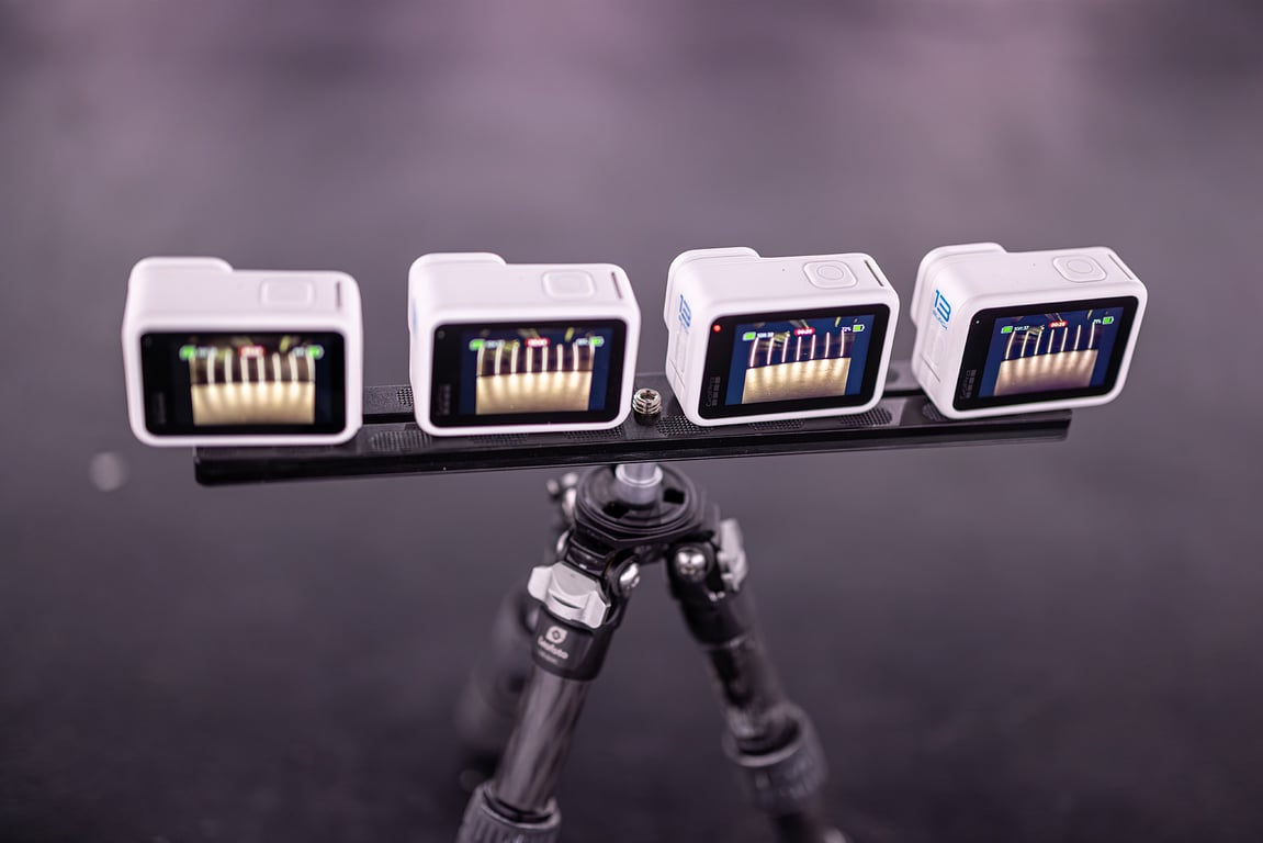
Camera Server supports GoPro cameras over USB and wireless transports. USB is the preferred path for dependable event work. Wi-Fi/COHN is available for managed networks and should be tested on the real event network before production use.
Supported models
- HERO11, HERO12, HERO13
- The legacy guide was tested with HERO13. Other models and firmware combinations need their own test before an event.
USB setup
For a first setup or a smaller rig:
- Connect the GoPro cameras to the Windows Camera Server computer with USB data cables.
- Accept the camera's terms and keep the default setup options.
- If the camera displays a QR-code page asking to connect to a phone, choose Back to bypass phone setup.
- Open Camera Server and confirm the cameras in Camera control.
- Reorder the cameras if the physical numbering does not match the Camera Server roster.
- Select the required trigger mode for the group, such as single photo or video, and run a test capture.
There is no separate camera configuration step required for the basic USB workflow, but camera settings can be changed from Camera control when the adapter exposes them.
Supported capture behavior
The current GoPro adapter supports the following capabilities where the camera model and firmware expose them:
- Photo or single capture
- Video capture
- Night mode where supported
- Camera settings changes
- Triggering
- Camera time synchronization where available below the trigger modes
- Normal Camera Server workflows such as playback, countdowns, sharing, lights, and trigger actions
Interval, JAF, and custom trigger sequences may not be available for every GoPro mode. Confirm the available trigger modes in the current Camera control UI instead of assuming that a mode from another camera adapter is supported.
USB hubs and larger rigs
Use powered USB hubs with enough current and bandwidth for the cameras connected to them. The legacy operating pattern was four cameras per hub, spaced across ports 1, 3, 5, and 7 when the hub layout supports that arrangement. Treat this as a starting point, not a guaranteed limit.
- Avoid unpowered hubs for a multi-camera rig.
- Keep the hub topology simple and label every cable and camera position.
- Test the exact hub, cable, and port arrangement under a complete capture and download load.
- For larger arrays, distribute USB hubs across Raspberry Pi clients and connect those clients to the Camera Server computer over Ethernet.
- Confirm that every camera is visible, triggers, transfers its files, and appears in playback before scaling the rig.
Raspberry Pi scaling
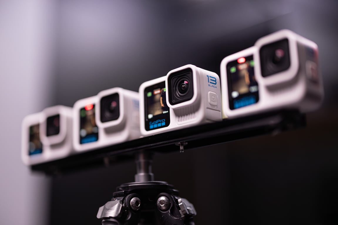
Raspberry Pi clients can extend a GoPro system beyond the number of cameras that one Windows computer can reliably handle through direct USB.
- Flash the currently supported XangleOS image for the node model.
- Update all nodes to the compatible current client version.
- Connect one or more powered USB hubs to each Pi, keeping within the measured power and transfer capacity of that Pi.
- Connect the Pis and the Camera Server computer through a Gigabit Ethernet switch.
- Open Network Nodes or the local-node settings in Camera control and confirm that every Pi is discovered.
- Assign each camera node to the correct group and run a complete multi-camera test.
The old guide used image and client version numbers that are no longer a reliable requirement. Use the current release guidance and the node diagnostics in Camera Server.
Example layouts from the legacy guide, retained as architecture examples rather than fixed prescriptions:
- 8 cameras: two powered USB hubs and one Windows computer.
- 24 cameras: six camera hubs connected through a distribution hub to a Windows computer.
- 48 cameras: distributed USB hubs on Raspberry Pi clients, one boot-server Pi where required, a 16-port network switch, and one Windows computer.
Measure each layout with the cameras, hubs, cables, network switch, and processing workflow you will actually use. More cameras increase power, bandwidth, transfer, and troubleshooting requirements.
Wi-Fi and COHN
Wi-Fi is an additional transport for the same GoPro adapter. It is not a replacement for the dependable USB fallback.
- Auto: USB first, then configured Wi-Fi/COHN endpoints.
- USB only: ignore Wi-Fi/COHN endpoints and keep USB discovery active.
- Wi-Fi/COHN only: ignore USB discovery and use configured wireless endpoints.
For a managed shared-router setup:
- Put the Camera Server computer on the rig router, preferably over wired Ethernet.
- Provision each GoPro onto that same network through the current COHN workflow.
- Reserve stable DHCP addresses for the cameras or configure the current static endpoint list.
- Select the corresponding GoPro connection mode in Camera control and save the settings.
- Confirm every camera's identity, IP address, transport, and enabled state.
- Test photo triggering and file transfer with two cameras, then four, before expanding the rig.
Do not use a camera's private hotspot as the normal multi-camera workflow. A single laptop Wi-Fi adapter can normally join only one GoPro AP at a time, and switching to an AP can disconnect the computer from the event network. Use AP mode only as a one-camera diagnostic unless the network design explicitly supports it.
For Wi-Fi photo capture, Camera Server can send same-delay trigger commands as an adapter-level fanout. This remains software timing over HTTP or HTTPS, not hardware synchronization. Do not promise millisecond sync over ordinary Wi-Fi.
Power and long sessions
For long sessions, test whether the camera and external power arrangement can operate without an internal battery. The camera, battery door, USB cable, hub, and power supply must all support the intended operating mode.
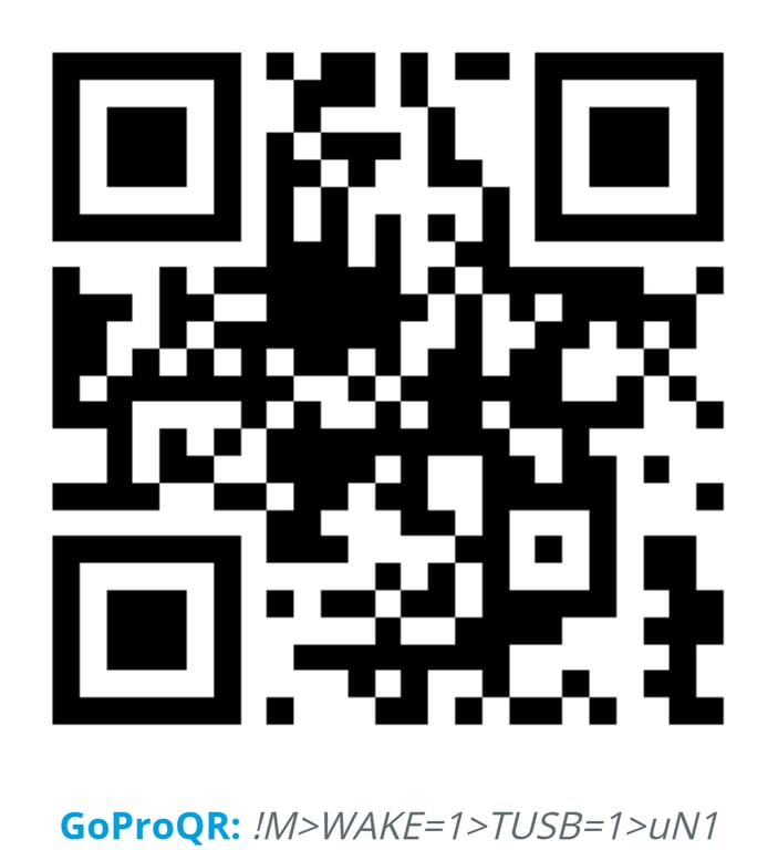
GoPro Labs firmware can expose QR-configured options for some camera models. The legacy guide used a QR command containing:
!MTUSB=1!MWAKE=2!MBEEP=0!MuN1
The intended meanings were:
!MTUSB=1: trust USB or allow operation from external USB power without the normal power handshake.!MWAKE=2: attempt to wake or power on the camera when USB power is present.!MBEEP=0: disable beeps.!MuN1: turn the camera off when USB power is removed.
These are GoPro Labs commands, not Camera Server settings. They depend on the camera model, Labs firmware, and the current GoPro Labs command syntax. Verify the command in the official GoPro Labs custom QR tool before applying it. Do not scan an unverified command into production cameras.
Use a properly rated external power supply. The legacy guide recommended at least 5 V and 2.4 A per camera path, but the correct requirement depends on the camera, cable, hub, and operating mode. Watch for heat, camera resets, missing files, and battery charging behavior during a long test.
Hardware checklist
- GoPro cameras with compatible firmware
- Windows computer running Camera Server
- USB data cables for direct connections
- Powered USB hubs for multi-camera USB rigs
- Raspberry Pi clients and a supported XangleOS image for distributed USB
- Gigabit Ethernet switch and reliable network cables for node layouts
- Optional Bluetooth presenter for a physical trigger button
- Optional upgraded battery doors or external-power accessories appropriate to the camera
The old budget spreadsheet and shopping links are not maintained requirements. Select current hardware from measured power, bandwidth, camera compatibility, and event-support needs.
Test before an event
Run this checklist on the exact rig:
- Confirm every camera is numbered and physically labeled.
- Confirm the selected GoPro connection mode: USB, Wi-Fi/COHN, or Auto.
- Confirm every camera appears in Camera control and belongs to the expected group.
- Set the capture mode and compatible settings.
- Trigger several captures, including the longest or highest-load mode planned for the event.
- Confirm every file transfers to the expected dataset and opens in playback.
- Test camera time synchronization if the workflow depends on it.
- Test countdowns, sharing, lights, and any external trigger action that will be used.
- Leave the rig running long enough to expose power, heat, network, and USB problems.
If timing is important, measure the result with the LED timer synchronization tool and treat the result as a measured property of that specific rig.