
Use a high-frequency LED timer to estimate the relative trigger timing of cameras in a multi-camera rig. Camera Server triggers the cameras; the timer provides a visible time reference that can be read from each captured image.
This is a measurement tool, not a Camera Server feature or a replacement for camera-node diagnostics. It measures relative timing in the images and does not by itself prove that every camera exposes at exactly the same instant.
Why use an LED timer?
The timing differences in a synchronized rig can be shorter than one millisecond. Ordinary clocks and displays that show milliseconds often refresh at only 30 or 60 Hz, so their visible state is not precise enough for this test.
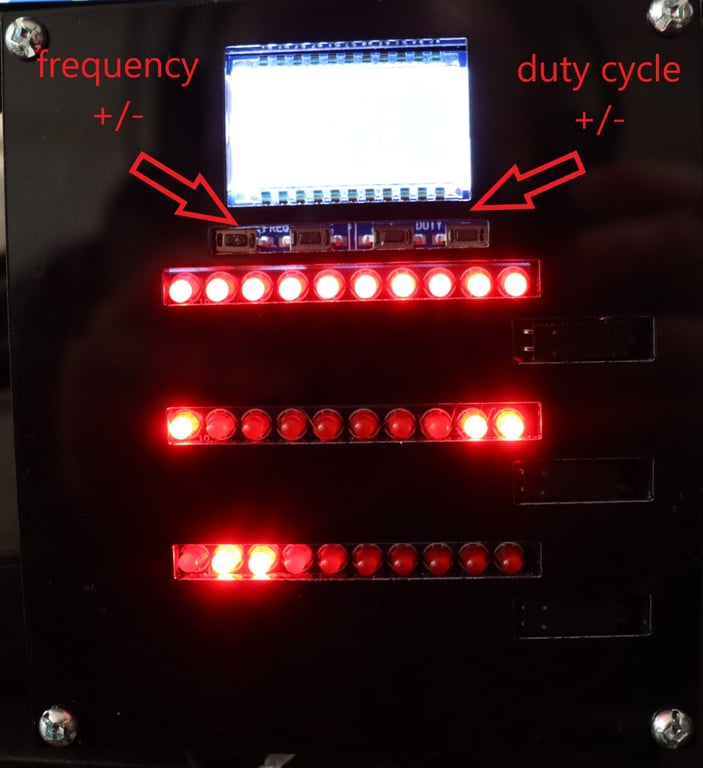
The custom timer used in the original guide has three rows of ten LEDs. The rows can be configured from 1 Hz to 10 kHz, with frequency and duty cycle adjusted using the controls below the display.
At a 1 kHz setting:
- The first row advances every 1 ms.
- The second row advances every 10 ms.
- The third row advances every 100 ms.
The timer can therefore encode a relative timestamp across the three rows when the cameras photograph it.
Prepare the capture
- Place the LED timer where every camera can see the same display and LED rows.
- Make sure the timer is stable, bright enough to appear in every image, and not clipped by the lens framing.
- Choose a timer frequency appropriate to the shutter speed and precision you need. Start with 1 kHz for a one-millisecond first-row increment.
- Set each camera to the same exposure, aperture, ISO, focus, and image format used for the test.
- Use an exposure no longer than one first-row increment. At 1 kHz, start around 1/1000 s and confirm the result in a test image. A longer exposure can illuminate several adjacent LEDs and make the column difficult to read.
- Adjust ISO and aperture so the illuminated LED can be distinguished without losing the row or column information.
- Trigger the cameras from Camera Server using the same trigger path and warmup configuration used in the rig.
- Capture enough repeated test datasets to distinguish a repeatable offset from a single missed or poorly exposed frame.
Do not change exposure, timer frequency, or trigger settings halfway through a comparison set. Record the values with the dataset.
Read the timestamp
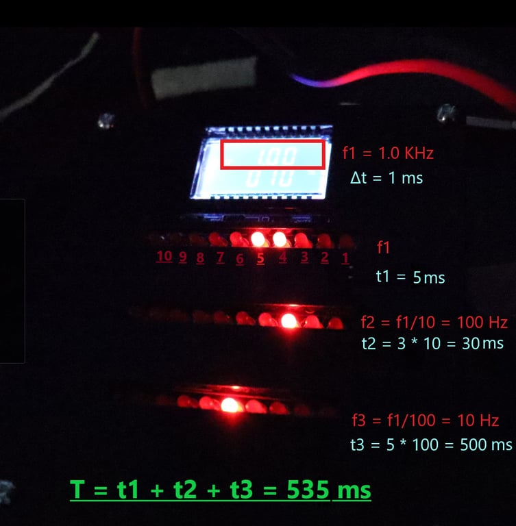
For each camera image, identify the illuminated LED in each row. Convert the three row readings to time using the timer frequency, then add the values together.
For example, at 1 kHz:
- A first-row position of 5 represents 5 ms.
- A second-row position of 3 represents 30 ms.
- A third-row position of 5 represents 500 ms.
- The relative timer reading is therefore 535 ms.
The exact first position and counting direction depend on the timer's labels. Use the same convention for every image in the comparison set and write the convention beside your measurements.
Calculate the synchronization spread
- Read the timer timestamp from each camera image.
- Record the timestamp beside the camera number and capture repetition.
- Find the earliest and latest timestamp in the same capture.
- Subtract the earliest value from the latest value.
- Repeat for several captures and compare the spreads.
The result is an estimate of the relative trigger or exposure spread visible in the images. It can reveal a camera that consistently fires later, but it cannot identify the cause by itself. A difference may come from trigger delivery, camera processing, shutter behavior, rolling shutter, exposure length, timer visibility, or image-reading error.
Make the result repeatable
- Keep the timer and all cameras fixed between runs.
- Use the same lens, focus, exposure, and lighting conditions.
- Test the complete trigger path, including Raspberry Pi or Windows nodes if they are part of the production rig.
- Check that every camera captured the same timer state and that no image was delayed by a reconnect or transfer issue.
- Repeat the test after changing one variable, such as trigger warmup or camera settings.
- Save the original images and a table of readings with the test dataset.
Use the measurement to compare configurations, not as a universal benchmark. A rig that produces a small spread with one shutter speed or timer setting may behave differently with another camera mode or exposure duration.